Welcome
To the web page of Mark, M0DFF
Locator JO02PW Last updated 19th June 2025
Copyright © M0DFF 2025
Yeo Notes 2
On the circuit diagram this possibility is indicated by arrows between C26 and C27. It is also shown in the RF bandpass filter section, but you have to be extra careful as there are now three “Capacitors, Fixed Resonating Value Nominal “ capacitors to be made up, this is shown on page 11 table 2. The principle remains the same, but note that there is in addition a fixed value of capacitance that is there as well, C50 and C57. These could be thought of as the equivalent of C3 in the VFO described above.
For 80m the VFO would need C26 and C 27 connected in parallel (each are 150pF) to give a total “Nominal Value” of 300pF. The RF bandpass filter would need C51 and C52 connected in parallel to give 300pF which in turn is connected in parallel with C22 (22pF) to give a total “Capacitors, Fixed Resonating Value Nominal “ of 322pF (close enough to the total “Nominal Value” listed in table 2 of 330pF)
For 30m the VFO would need C26 and C27 connected in series (each are 150pF) to give a total “nominal Value” of 75pF. The RF bandpass filter would need just C51 or C52 (22pF) connected in parallel with C50 (also 22pF) to give “Capacitors, Fixed Resonating Value Nominal “ of 44pF (close enough to the total “Nominal Value” of 40pF listed in table 2)
Note from Table 1 and 2 that not all capacitors may be connected for a given band, read the table carefully.
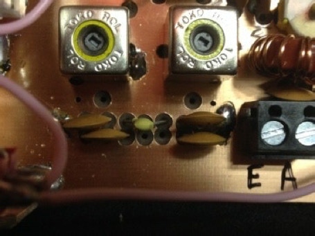
Below is a photograph of the component placement for the RF bandpass filter 40m option.